Earthworks Theories
Three methods are available in our earthworks software ZeonEarth
Normally earthworks softwares will only provide one method of quantities takeoff. Any one of the method list below. But our ZeonEarth which special, it can provides these three methods together. Where it gives user more option in earthworks computation. Therefore, the results calculated can give confidence to user.
- 3D method/Digital Elevation Method
- Grid method
- Cross section method
Theory Behind
3D Method/Digital Elevation Method
It is new method which handles by computer. It is not for human. It needs computer to do such computation. Performance of computation depends on computer hardware. The larger project size will consume more memory and processing power.
The main algorithm of computation is using solid triangulation. It is used to represent the earth surface or part of the surface digitally.
The Zeon Earth uses solid triangulation to compute the volume of cut and fill. By using of 3 points in triangle, average heights are compute for existing and proposed levels.
Then compute the volume by multiple the average height with area of triangle.
Our Zeon earth is used this methodology to work on. First of all, This CAD drawing is taken from surveyor where all the survey points are shown in CAD. All these points will be existing levels. Then designer need to place in all new
proposed level points into CAD drawing. It can as simple as TEXT entities in CAD with specific layer name. Then Zeon Earth will go into CAD drawing to read out all points belong to existing and proposed levels.
First task will be triangulate all existing levels. After that, Zeon Earth will reorganize these points to joint all together. All proposed levels which not fall exactly on existing point will be interpolated. It calculates by
interpolate the value in one of existing triangle. Later, re-triangulate these points. New triangles will be formed. Finally, each triangle will has two Z levels. One is existing level and the other one is proposed level.
Based on three points on triangle, volume can be computed.
For example, surveyor did survey on a site with 5 points. Surveyor will convert these data into CAD drawing. This drawing will then forward to earthworks designer to do earthworks design.
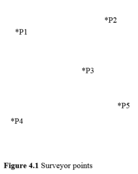
When we want to use this triangulation method, these five points will be connected by line and turn into four triangles. There are many methods to generate these triangles. One of the famous methods is Delaunay Method.
For more information on this method, please refer to any document on Delaunay method.
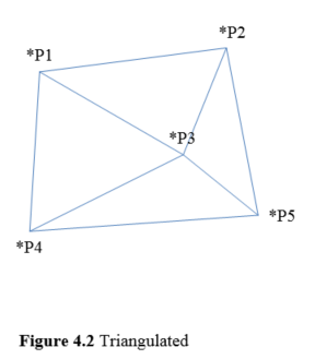
After triangulation, the next step is to determine the proposed levels for these points. As a result, every coordinate will has two Z levels. One is existing level and another one is proposed level.
Whenever, levels are identified, volume on each triangle will be determined by using principle below. Each triangle volume will be calculated. Total up all triangles will provide total cut or fill volume.
Grid Method
It is one of traditional method to calculate earthworks. This method is used to obtain the volume of large are of excavation such as basement, housing development and so on where the formation level can be sloping, horizontal or terraced.
The grid method involves drawing a uniform grid onto a plan of the earthworks project, and taking off the existing and proposed ground levels at each node of the grid. With these values the average depth of cut or fill required on each cell
of the grid is calculated, and the volume for each cell is obtained by multiplying the depth by the cell area. By adding the volumes for each cell together the total cut and fill volumes for the project can be estimated.
Basically ground and proposed levels are taken at each grid intersection by method of indirect contouring. By reducing the size of square or rectangular, better accuracy in volumes can be achieved. However, the accuracy of results should be
determined as the circumstances required for reducing the size of square or rectangular means more work is involved. It will be a signification difference of result by using large grid system compare to small grid system in a hilly area
instead of flat area.
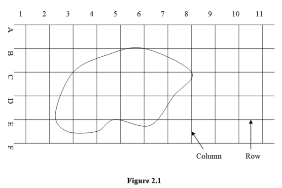
An area to be calculated shown with existing and designed levels by contours and platform levels is divided by equidistant vertical and horizontal grids that are known as columns and rows respectively. These columns and rows should be drawn
to extend beyond the boundaries of the area so that the whole area is covered by this so called grid system (Figure 2.1).
The columns and row s are then numbered numerically or aphetically from left to right for columns and top to bottom for rows.
Cross Section Method
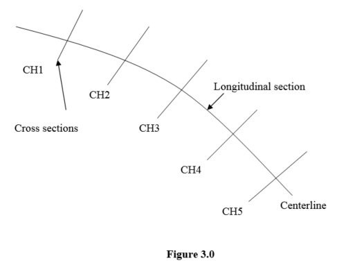
Another popular traditional method is cross section method. This method is useful for highway construction projects. They can take a number of difference forms and they are normally based on longitudinal sections. In the construction of a
road, railway, large diameter underground pipeline, having set out the proposed centre line on the ground, levels are taken at regular intervals both along it and at right angles to it to obtain the longitudinal and cross sections.
This is shown on Figure 3.0.
The cross section method involves plotting cross sections of the existing and proposed levels at regular intervals across the project site. For each of the cross sections, the cut area and the fill area is determined. The volume between
each pair of sections is estimated by multiplying the average cut or fill area of the two sections by the distance between them.
When preparing the longitudinal section, the vertical alignment is designed and the formation levels along the centerline are calculated. A typical longitudinal section showing the formation level is shown in figure 3.1.
Each cross section (CS) is drawn and area between the existing and proposed levels is calculated. Figure 3.1 shows one typical cross section.
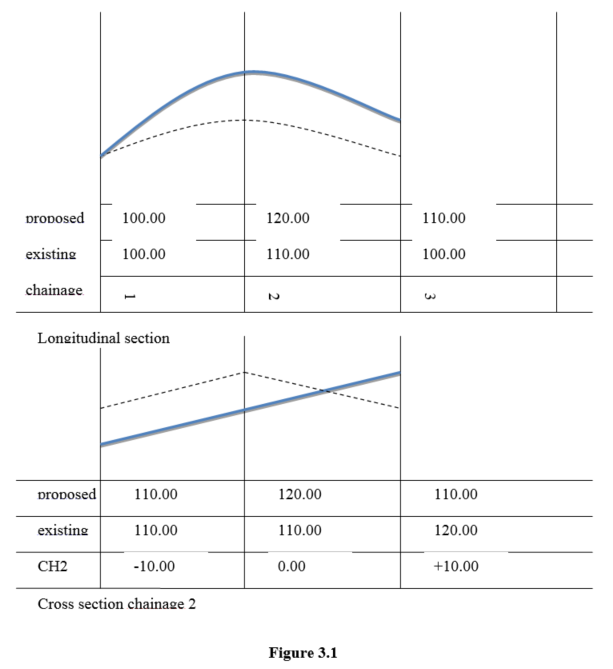
Both the longitudinal section and the cross sections are usually drawn with their horizontal and vertical scales at difference values.
As with the grid system method, the cross-sections are comprises of total cut/fill section, partial cut and fill as per discussed in grid system method.
Advantages and Disadvantages
3D Method/Digital Elevation Method
- Advantages
It provides fast earthworks computation by using computer.
It can works on any shape of site.
It can achieve high accuracy.
It can resolves issue on split level where grid and cross section method cannot achieved.
Disadvantages
It cannot do it by manual computation. It is due to too many irregular shapes. Human cannot easily read on those irregular shapes.
It must uses computer to do computation.
Cost of software license is vary between USD$200 to several $1000s.
It is difficult to manually validate the result.
Grid Method
- Advantages
It provides fast earthworks computation.
It can easy to work out the earthworks.
It can use a larger grid system on flat area where the result of earthworks is not signification as compare to smaller grid system.
It can easily handle by manually.
It more suitable to use in housing development.
Disadvantages
It cannot capture the problem of split levels, slopes.
It will have signification result on hilly area by setting a larger grid system compare to smaller grid system.
It is not practical to apply it to the road design.
Cross Section Method
- Advantages
The flexibility of cross section method can help engineer to capture the irregular land.
Problem such as split levels and slopes area can be easily solved. But not in the direction of longitudinal.
It is good to use to road or highway design.
Disadvantages
It is needs more time to handle the cross section method.
Fresh graduate engineer may need more time to understand the concept of cross section method as compare to grid system method.
Whenever there is a sharp turning point, cross section method will has problem in compute volume. Confliction of cross sections plot.
The sections need to takeoff must in term of similar width. i.e. takeoff cannot be carried out say first section with width of 20m, second section with width of 10m, third section with 40m etc. These cannot provide correct result where the widths are not similar.
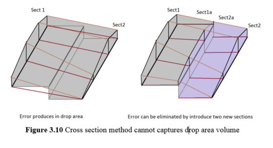
Whenever along longitudinal direction of cross section being captured with drop happened (Figure 3.10), there will be error to be produced where cross section cannot calculate the missing volume. The missing volume can be eliminated by introduce two new sections at the drop area.
Slope
Pitfall of slope
- 2D and 3D Slope
One of the important element in earthworks is the slope. Traditionally, engineer will draw the estimated slope in 2D layout. Somehow, there will be a “loophole” that the estimated slope will has problem in reality. i.e. during construction, the slope cannot be constructed due to geometry issue. This problem only can found out during construction. Earthworks contractor will come to engineer to highlight the constructability of slope. In a way, it will incur additional cost due to unforeseen this problem. This will be difference when the earthworks can be model in 3D with slope. All such “loophole” can be tackle immediately without wait until the construction stage. The 3D model is important in earthworks, it can help engineer, client or contractor to understand how the earthworks to be look alike in real world. Our ZeonEarth with Zeon technology, it can easily presents the 3D model and tackle the slope constructability issue.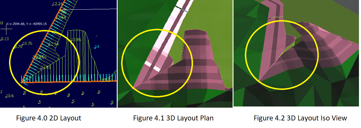
Figure 4.0 is the 2D slope layout. It looks prefect in 2D. Figure 4.1 is the 3D layout plan view. It also looks prefect. But the Figure 4.2 is the 3D isometry view, here you can visualize the constructability of slope. It means that it cannot be constructed in reality. This is one example where slope problem cannot be proper tackle in 2D plan.